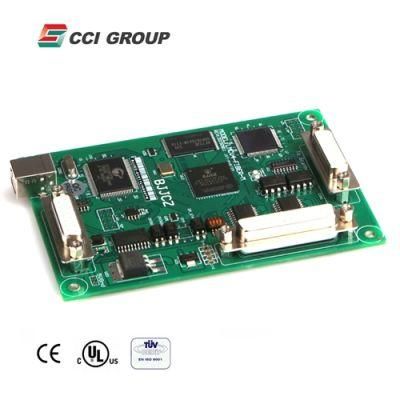
Laser Marking Machine Parts Original Bjjcz Ezcad Fiber Laser Control Cards
Shandong CCI Co., Ltd.- Warranty:12 Months
- Customized:Non-Customized
Base Info
- Model NO.:FM-30
- Standard Component:Standard Component
- Type:Laser Control Card
- Transport Package:Carton
- Specification:200*100*50mm
- Trademark:BJJCZ
- Origin:China
- HS Code:8466939000
- Production Capacity:1000 Sets Per Month
- Package size per unit product:20.00cm * 15.00cm * 10.00cm
- Gross weight per unit product:2.000kg
- Lead Time:3 days (1 - 1 Sets)
Description
Basic Info.
Model NO. FM-30 Standard Component Standard Component Type Laser Control Card Transport Package Carton Specification 200*100*50mm Trademark BJJCZ Origin China HS Code 8466939000 Production Capacity 1000 Sets Per MonthPackaging & Delivery
Package size per unit product 20.00cm * 15.00cm * 10.00cm Gross weight per unit product 2.000kg Lead Time 3 days (1 - 1 Sets)To be negotiated ( > 1 Sets)
Product Description
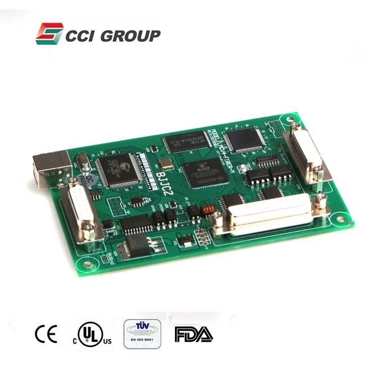 1. Feature:Standard DB25 connector, can be wire to IPG laser directly. Galvo control signal is digital, which can be connect to most scanhead directly.on-the-fly marking feature. A encoder can be used to surveillance the pipeline speed real-timely.Multiple boards on 1 computer: One computer can control up to 8 control board to mark different pattern simultaneouslyExtension axis(step motor or sever motor): two set of direction/pulse signal can be used to control 2 step(server) motors.6 general input signals(TTL campatible): In0-In3, XORG0(IN14), IN15.2 general output signals(TTL campatible): OUT4-OUT5 coming out of Con4.Remark function: this function is used to remark what ever is in the memory of the board, especially convenient for high speed marking of a same pattern.Compatible with USB2.0 specifications.
2. Main Structure Size
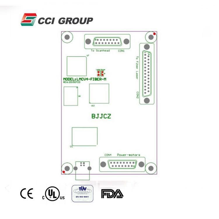
3. Case:
Fiber Laser Marking Machine
4. Electrical Wiring-Pin Definition
4.1 power supply
The control board need a 5V DC power supply. We recommend a 5V/3A DC supply. The Vcc and Gnd pin are 4/5 and 12/13 of CON4 respectively.
| CON4 pins | Name | Function |
| 4, 5 | VCC | +5V power supply. |
| 11, 12,13 | GND | Reference ground of the power supply. |
4.2 CON1: DB15 scan head control
The signals that control scan head are digital, therefore can be connected to the digital scan head directly. Because the protocols that every manufacturer used are not always the same, you need to conform which protocol is used. We also provide a D/A converter in the package. The digital signal converted by which can be connected to a analog scan head.
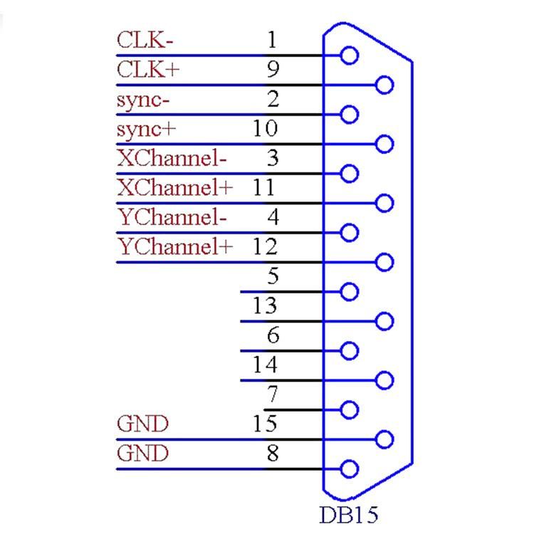
| Pin | Name | Function |
| 1,9 | CLK- / CLK+ | Clock signal- / Clock signal+ |
| 2,10 | SYNC- / SYNC+ | Synchronization signal - / Synchronization signal+ |
| 3,11 | X Channel- / X Channel+ | Scanhead signal X- / Scanhead signal X+ |
| 4,12 | Y Channel- / Y Channel+ | Scanhead signal Y- / Scanhead signal Y+ |
| 5,13 | Z Channel- / Z Channel+ | Scanhead signal Z- / Scanhead signal Z+ |
| 6,14, | Status-/Status+ | Reserved |
| 7 | NULL | Reserved |
| 8,15 | GND | Reference signal |
4.3 CON2 :DB25 Laser Control
CON2 socket can be connected to the DB25 connector through a pin to pin cable.
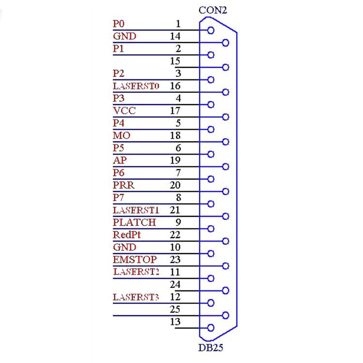
| Pin No. | Signal | Illustration |
| 1--8 | P0--P7 | Laser power signal.TTL compatible |
| 9 | PLATCH | Power signal latch. TTL compatible. |
| 10, 14, | GND | The reference ground of the control board. |
| 11,12,16,21 | LASERST0~3 | Alarm signal of Laser module |
| 17 | VCC | 5V power output. |
| 18 | MO | Main oscillator signal. TTL compatible. |
| 19 | AP | Power amplifier signal. TTL compatible. |
| 20 | PRR | Pulse repetitive rate signal. TTL compatible. |
| 22 | RedPt | Red light pointer signal. TTL compatible. |
| 23 | EMSTOP | Emergency stop signal. TTL compatible. |
| 13,24,25 | Unconnected. |
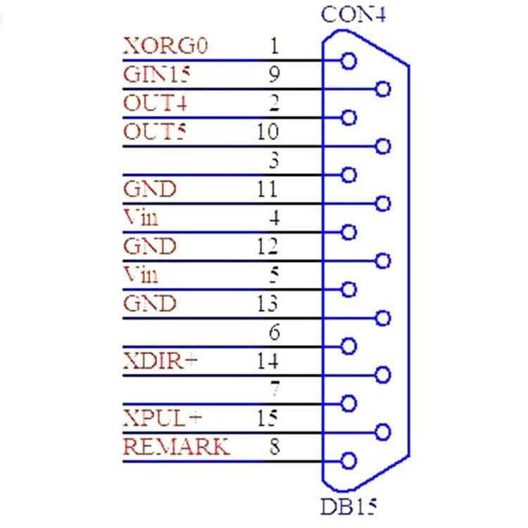
| Pin | NAME | Function |
1 | XORG0 | The home signal of extension axis X. To use this pin just connect it and GND to a switch. In software In14 represents this pin. |
| 2 | GIN15 | General input in15, using GND as a reference ground. |
| 2,10 | OUT4, OUT5 | General Output Out 4-Out 5, using GND as reference ground. They are all TTL output . |
| 4,5 | Vin | Input pin for 5V power supply. |
| 11,12,13 | Gnd | Reference ground of 5V power supply |
14 | XDIR+ | Direction signal of extension axis X. It is a TTL output. For common anode, use VCC and XDIR+ signals, and VCC is anode signal. |
15 | XPUL+- | Pulse signal of extension axis X. It is a TTL output. For common anode, use VCC and XDIR+ signals, and VCC is anode signal. |
8 | ReMark | Repeat marking signal. Use GND as a reference ground, to use this signal just connect a switch between this pin and GND. When it is activated the control will mark the content in the cache. |
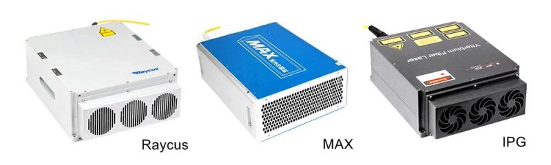
5.1 Laser Source: Raycus/ MAX/ IPG
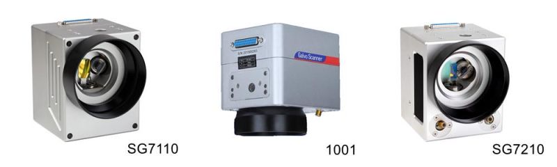
5.2 Galvanometer Scanner: SINO-GALVO
 5.3 Field Lens: WAVELENTH
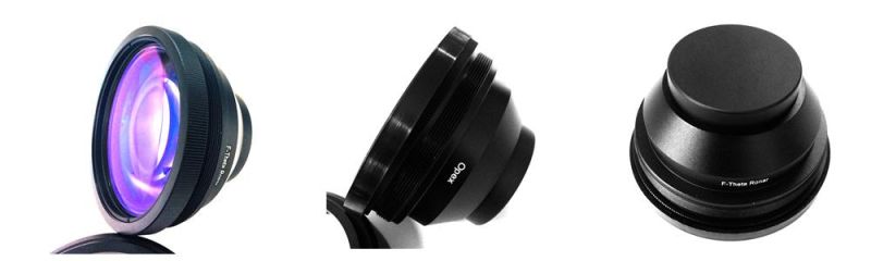 5.5 Rotary Device (If need)
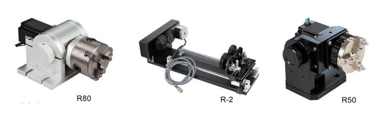 6. Contact Information
 To be continued..